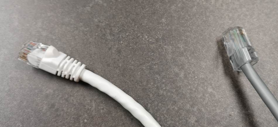
At some point, you’ve probably heard the word ethernet and wondered what that means. In science, ether was a made-up material that physicists used in thought experiments. It was hypothesized to fill all space, and it provided a hypothetical medium for heat and light to travel through, like how sound travels through water.
Ethernet is part of the OSI Model for networks and provides the medium for your data to travel through. It includes the first OSI layer, physical electronics, and the second OSI layer, signaling. The standard for the two OSI Model layers that comprise ethernet is called IEEE 802.3.
Really quickly, the OSI Model is simply a framework for designing anything network capable that covers everything right from the electronics to the software. It’s a model used to ensure that network equipment and software created can work together without issue.
Even though ethernet includes layer one and layer two, the model has a total of 7 layers. See the full model towards the end of this article.
OSI Model Level 1: Physical Electronics
The physical electronics used in ethernet, from a user perspective, involve network interface cards, media converters, and network devices with built-in network ports. Network capable devices like printers, cameras, or game consoles have network interface cards built-in that let them physically be part of a network.

Typically all laptops and desktops come with a built-in network interface card or NIC with an ethernet port and the supporting electronics built-in. A NIC is also something you can buy for your computer separately if you would like to upgrade speeds or need more than one.
Usually, you only need one, but it can be useful for specific special applications to have two or more. Anything that communicates using wired ethernet and has the ethernet cable port also has the electronics for ethernet. The electronics get built into the device.
The most common connector used today for standard home user computers is the RJ45, and they are on copper cable connections. You can read more about cabling here.
Sometimes, it can be necessary to use different cable types in parts of the network in the workplace because some cables have length limits and the data networks are physically large. Network cable sections longer than length limits are where media converters can be handy.

Media converters are usually small devices that let you switch between cable types. They typically need to be plugged into a source of power to do their job. They allow people to connect one kind of cable or media to another type of cable or media. They do this by having a connector for each type of network cable and passing the data through itself as it comes.
A common situation is the need to be able to convert between copper cabling and fiber optic cabling. It used to be more common to see media conversion to coax cabling, and media converters supporting coax cabling still exists today. Just in less abundance.
Media conversion may be necessary when data networks are designed using copper cabling because the price is low. But then there may be one or more points you need to connect located over the distance limit for copper cables. What do you do in those cases?
The easiest solution is to use fiber optic cabling for the long spans and then connect it to your copper network using a media converter on either end. That cost-effectively allows us to mix the benefits of fiber optics with the practicality of copper.
OSI Model Level 2: Data Link Layer
Level 2 is all about data flow basics and sharing the connection amongst various applications or network users. In addition to this, the data link layer provides error correction on the sent data. Error correction means that if something happens where the data gets altered during transmission, it’s fixed on the fly.
In terms of sharing, two things need to be shared. Access to and use of electronics on your computer by applications and the network by different network users. Because these are so different, they got broken out into two separate sublayers.
The first sublayer is media access control or MAC. The MAC sublayer is the sublayer that outlines access to and usage of the NIC. It controls the electronics and manages connections to and from your computer.
As part of this, each device has a Media Access Control address or MAC address. These identifiers are addresses assigned to each device in the factory. No two MAC addresses are alike, giving each device a unique address.
The second sublayer is called logical link control or LLC. This sublayer defines access to and usage of the network at the switch and plays a role in how data networks can get divided, shared and administered. We place tags on the small packages of data sent out on the data network to use the logical link layer. It lets the network switch and other network switches know how to handle the data received.
This data network discussion level is a bit advanced, but managed switches can accept configurations to use this information in your network design. So managed switches let you be intentional and manage the data flow and access to your network.
It’s important to note that ethernet still functions fully with only media access control. The way it’s designed, that’s enough However, it means that the logical link control tags will be blank, and managed switches can’t be used to control your network traffic. That’s just fine from a simple network operation standpoint, which concerns most home users.
OSI Model Level 2 Devices
Besides the network interface card or NIC on level one, the following central device is called a network switch, which operates on level two. A network switch acts like a repeater or a hub connecting multiple devices forming the network. It does its job by recognizing and connecting devices using media access control.
The most commonly available switch is an unmanaged switch. ‘Unmanaged’ means it can’t take a configuration to manage traffic using logical link control. It comes with base functionality, and that’s it. For most people, that’s all that they need, especially at home. You can connect your devices to it, and it just works.
The place you’ll most commonly find these unmanaged switches is built into a home network router. A router is a level 3 device because it operates above level 2, but that’s why you have different ports on your router. The WAN or wide-area-network port is what you connect to your ethernet modem.
The network router portion of the device sits internally between the WAN port and the switch. The other external ports to which you can connect your devices to are for the network switch.
Depending on what you’re doing at home, you may find that you need an additional network switch. In this case, it’s perfectly acceptable to use the network switch on an old router, or you can easily find inexpensive unmanaged switches to purchase.
A managed switch lets you do a few useful things, but an essential feature is to separate your switch’s traffic into groups called virtual LANs. This feature is in the logical link control domain and lets you place a tag on the data passing over the network. The tag allows the managed switch to control speed and access across the network.
Admittedly, this is a bit advanced for the home user, so we’ll leave it there, but it is still good to know it exists. If you’re hungry to read more, you can search for logical link control, VLAN’s, or virtual LAN’s.
The OSI Model Layers
The whole OSI Model is seen here in this table. This table isn’t specific to the topic at hand. The only reason to include it is to see how the model levels all work together and visualize how ethernet fits. The different layers are essential to the networking world but have enough depth to have separate articles.

Congratulations! You now understand the basics of ethernet. Now when you read information about network devices or people discuss networks, you’ll know what this word means.
